
Download the product manual here.
Box Contents:
Two (2) Boards; one with varying impedance and one with ‘flat’ impedance
DEMONSTRATION CIRCUITS
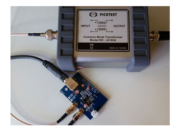
Provisions are included for a Bode plot measurement, with the injection resistor, R5, included as well as test-points for the injection signal and measurement (TP3 and TP4). SMA output connectors are also included to simplify connections for many measurements including the 2-port output impedance measurement, step load and other common measurements.
The board is USB powered by connecting a USB cable with a type B connector to the power connector USB1. (CAUTION: R9 and R10 GET HOT - DO NOT TOUCH)
| Test Points | Function |
| TP1 | Input voltage meter or probe |
| TP2 | Ground for meter or probe |
| TP3 | Bode injection |
| TP4 | Bode injection |
| Model | Description | Price | |
| LM20143B | LM20143B VRM Demo Boards V1.0(Flat and Varying Impedance) | $199.00 |
The circuit is an integrated point of load synchronous buck regulator with a 5V input and a 1.2V/2.5A output. The device uses emulated current mode control, making it simple to create a flat impedance output. Easily accessible 0805 chip size components make it easy to customize or experiment with different component values. This is a fully self-contained demo board using USB input power and an on-board resistive load.
Supported Measurements
TEST |
SIGNAL INJECTORS NEEDED |
| 2-port output impedance | J2102A two SMA cables (optional two P2130A or J2130A) |
| Load Step | J2111A or J2150A and J2130A or P2130A SMA cable |
| Ripple and Noise | J2130A or P2130A SMA cable |
| Turn on overshoot | Scope with probe or SMA cable |
| PSRR | J2120A or J2111A and two voltage probes |
| Input Impedance | J2120A voltage and current probe |
| Bode Plot | J2100A or J2101A two voltage probes |
Copyright © 2023 Picotest. All rights reserved.
