![Water-cooled browser probe head [P1205A stepper head]](images/Water_Cooled_Probe_head_B.jpg)
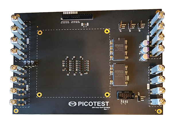
GaN “VRM+PDN Validators” in different formats to support different current levels
BENEFITS:
KEY FEATURES:
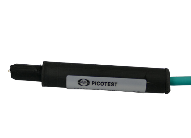
P2105A Browser Style Probe Head-Based Solution (S10)
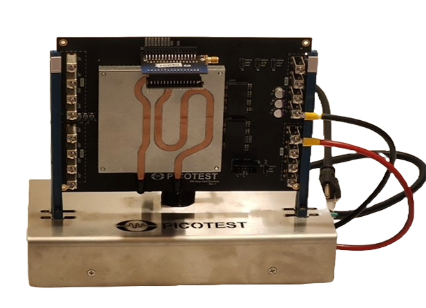
Water-Cooled Probe Head-Based Solution (S50)
Load Board Solution (S2000)
Applications:
What's included:
P2105A Solution (Model S10)
Water-Cooled Solution (Model S50)
Load Board Solution (Model S2000)
| Model | Description | Price |
| S10 | P2105A Probe-Based Stepper < 10A Applications | Request a Quote |
| S50 | Water-Cooled Head Stepper < 50A Applications | Request a Quote |
| S2000 | Load Board Development < 2000A Applications | Request a Quote |
Transient Testing
Transient load current step testing is a critical part of power system design, test, and verification. No matter the architecture, design make-up, or power levels, transient testing is key to evaluating many aspects including power integrity, power distribution network (‘PDN) validation, Voltage Regulation Module (‘VRM’) stability and transient response, noise, large-signal control loop stability, input filter stability, load emulation, thermal (TDP) testing, and IC package performance.
Picotest’s line of transient steppers enable testing of very fast load current transitions, high peak and average power, via multiple form factors that previously were unavailable or impractical to accomplish. In particular, demanding low-voltage, high-current applications including those found in data centers, AI, graphics, EV, and servers can now be tested, including crosstalk, thermal performance and EMI, long before the final ASIC is even available.
The power distribution networks that provide power to advanced digital loads such as CPUs, GPUs, ASICs, FPGAs, and other custom ICs can now be validated before the costly ICs are exposed to any power system related unknowns.
Product Selection
The product line provides load step testing orders of magnitude faster and higher than previously available. Three product levels are available based on load current and delivery form factor: less than 10A, 10A-50A, and up to 2047A. Picotest offers both open and closed-loop load current control options. The open loop stepper is essentially a signal level voltage controlled switch that opens or closes a path from the power rail through a GaN FET and custom resistor. So, while the probe can be moved to rails of different voltages and the step current will vary based on the power rail voltage. The baseline load current is set at the time of purchase for a specified voltage-current combo resulting in fixed resistor values in the probe. The resolution is set by the resistor array Picotest offers up to 11 bit, 66MSPS control, emulating many different waveforms. Closed loop current control uses OPAMP feedback and custom, three terminal sense resistors, allowing up to 100MHz analog bandwidth. The power density is much lower for closed loop control than for open loop control while the cost for closed loop control is higher than for open loop control.
The S10 under 10A solution is a hand-held browser style probe format that fits into tight places. The open-loop current step is a single pre-defined (at the time of purchase) current step, determined by the custom resistor selection. Note, since this is an open loop stepper, the current is dependent on the voltage of the power rail. The S50 10A-50A solution is a water-cooled browser-style probe format with 6 user pre-defined current steps (6-bit logic level control). Again, the current is dependent on the voltage of the power rail.
The S2000 (up to 2047A) solution is provided as a custom in-socket, ASIC replacement. This is in the form of a PCB connecting to the customer’s power board through a custom interface. Picotest will work with you through the development process to achieve a solution with appropriate performance, control, and integration.
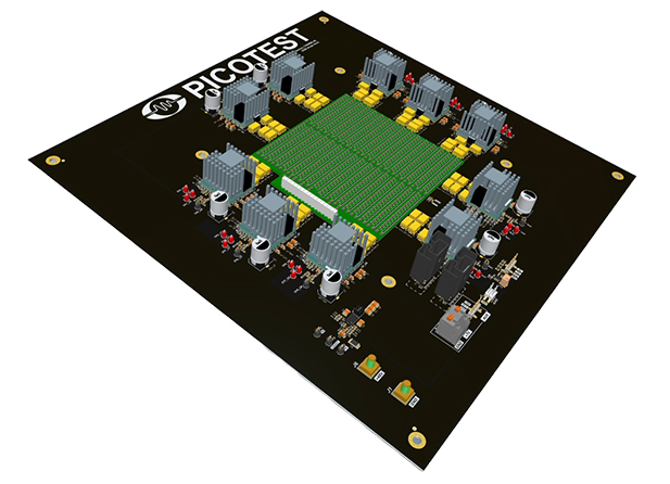
This step loader replaces the ASIC that normally loads the power rails, allowing thorough power rail validation including load line testing, large signal impedance, thermal testing, crosstalk assessment and EMI. This solution allows programmed and custom load current profiles from 0 to 2047A average in 1 Amp steps and 66MSPS using an 11-bit controller and custom design GaN/resistor networks.
P2105A Browser Probe (S10)
This is a hand held or probe stand held probe that can be used to quickly step multiple rails. It has 2 pins (+/-) and is placed across the power rail. The current step is controlled by a control wire pair (5V 50 Ohm signal). The current step (current sinking into the positive pin) mimics the control signal.
Water-Cooled Browser Probe (S50)
This is also a hand held or probe stand held browser probe. It behaves in a similar way to the P2105A. It comes with a water-cooler that enables the load current/power density to be higher. The current step (current sinking into the positive pin) is controlled by a control wire pair. This is a 6 bit control bus with 3.3V or 5V logic level. There are 6 switches and each can be turned on or off and each can have a level set at the time of manufacturing. So, there are 6 discrete levels that can be switched individually or combined to achieve up to 50Amps.
Custom Load Board Development (S1000)
This is generally a full custom solution. It consists of a power board that is designed and fabricated in a BGA pattern to be able to load the power board as ASIC package speed. The Picotest load board circuitry can be integrated onto your board or configured as a daughter card that mates with your power board directly or through a custom elastomer/connector interface. Each supply point is driven by one or more GaN cells which are essentially switches that can be configured to any voltage. The load current delivered can be modulated in just about any way with a custom 11 bit controller to drive the GaN cells on and off at up to 66MSPS. The specifications of the rates, speeds, and current/power levels are shown in the detail specification section.
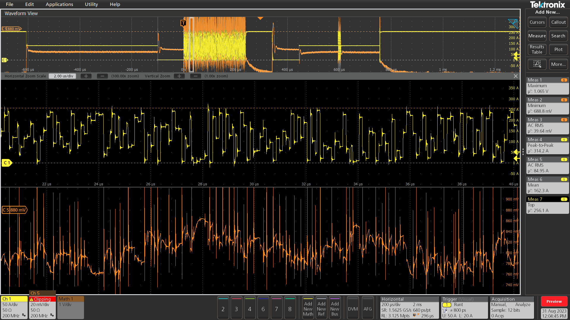
350MHz Pseudo Random Load Current Pattern
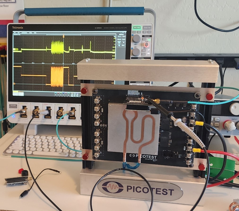
Picotest GaN Load Stepper Technology
Picotest’s line of load steppers utilize custom GaN technology and innovative power delivery interconnect formats and cooling to meet the requirements of supplying step load currents. Power levels up to 2000 Amps, 2000W average power (125W-125A/in2), up to 100% duty cycle, load current step rates that are sub-ns (<500ps), with DC – 50MHz repetition rates. These edge rates and average power levels exceed current capabilities by orders of magnitude.
The Picotest load steppers solve several pressing hurdles for power integrity testing. Electronic loads are too slow and present too much capacitance to allow a valid measurement to take place. Their edge rates are too slow to address the bandwidths needed to test PDN performance. They are unable to achieve the average and peak power levels needed. Additionally, the overly inductive interconnections between industry standard load step generators also make them too slow.
To achieve these performance breakthroughs, Picotest pushed the limits of GaN density, developed custom resistors, developed advanced cooling techniques, and integrated high-speed digital control. The result is a miniaturized load cell that can be replicated and scaled from a single cell to an array of 512 load cells in a 100mm x 100mm socket. Various form factors including novel probe heads were developed to allow load step testing on a rail-by-rail basis. Key to getting the edge rates necessary to test the high bandwidths associated with low voltage PDNs was the reduction to near-zero inductance of the interconnect between the steppers and the PCB where the load step is applied. Given the minimization and very high-power densities, custom water and refrigerated cooling schemes were also implemented. Due to the varied nature of the power system architectures, care was taken to allow most of these features to be customized to application requirements.
New techniques to minimize interconnect inductance, allowing fast-edge (<500ps) transient load currents to be delivered to the power supply rail include browser probes, water-cooled probes, and custom-developed load boards.
Application Notes
Evaluating Voltage Regulator Stability Using Step Load Testing
P2105A Browser Probe (Model S10)
| Characteristic | Rating | |
| Edge Rate (R/F time) | <500ps switching * | |
| Repetition Rate | DC-50MHz (Limited by average power and dwell time) | |
| Control | User Supplied - 5V pulse generator | |
| Maximum Dwell Time | 100us dwell | |
| Input voltage rating | Based on custom resistor * | |
| Output current rating | Based on resistor up to 10A | |
| Wattage | <1W avg. | |
| Voltage | 0.8V - 72V | |
| Connector Type | SMPM pulse, spring tip | |
* Final signal edge speed is dependent on the load board design, voltage, and current.Solution is single level (On/Off). Resistance is set at the time of manufacturing.
Water-Cooled Browser Probe (Model S50)
| Characteristic | Rating | |
| Edge Rate (R/F time) | <500ps switching * | |
| Repetition Rate | DC-50MHz (Limited by average power and dwell time) | |
| Control | User Supplied - Digital logic generator or Micro-controller (3.3V or 5V) | |
| Maximum Dwell Time | Up to 100% | |
| Input voltage rating | Based on custom resistor * | |
| Output current rating | Based on resistor up to 50A | |
| Wattage | <50W avg. | |
| Voltage | 0.8V - 72V | |
| Connector Type | SMPM pulse, spring tip | |
* Final signal edge speed is dependent on the load board design, voltage, and current. A 6-position water-cooled sub-ns browser step load probe. Resistance is set at the time of manufacturing. Any of the 6 resistors can be any value, they don’t need to be the same.
Ultra-High Speed Step Loaders - In-Socket (Model S2000)
| Characteristic | Rating | |
| Edge Rate (R/F time) | <500ps switching * | |
| Repetition Rate | DC-50MHz (Limited by average power and dwell time) | |
| Power level (continuous/instantaneous) | Up to 2047W Average | |
| Bandwidth - Duty Cycle/On/Off time range | UP to 100% Duty Cycle | |
| Input voltage rating | Based on resistor, default is 0.8V | |
| Output current rating | Based on resistor - up to 2047Amps | |
| Current Resolution (steps) | Up to 11-bit (Up to 2047Amps in 1 Amp Steps) - 50MSPS logic driven pattern generation | |
| Control | User Supplied - Digital logic generator, Micro-controller, or FPGA (3.3V or 5V) | |
| Connector Types | (Load) User-Defined and Supplied - Fixed pattern or custom patterns available (Control) 16 pin Header |
|
Copyright © 2023 Picotest. All rights reserved.