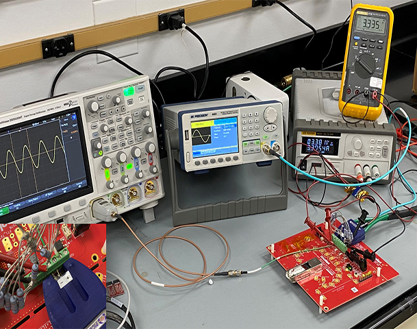
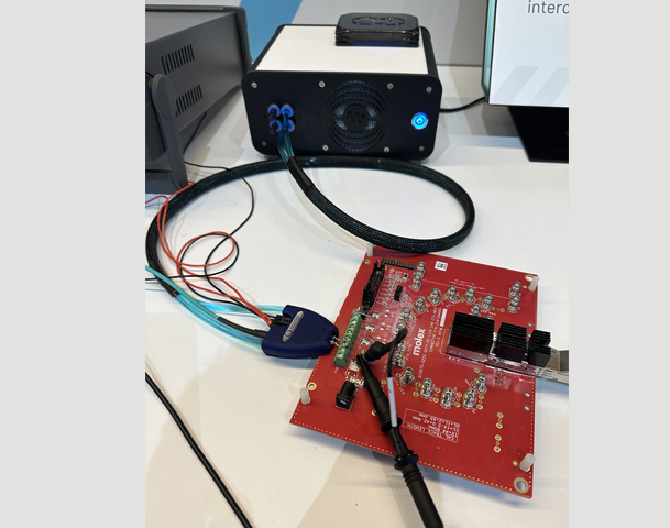
High Speed Line Modulator including Probe, Cooling Unit, Cabling, P9610 Power Supply (includes the USB and GPIB Interfaces, PWR-OPT02), and PWR-OPT05 Remote Sense board
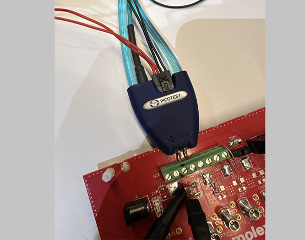
The P2124A is a GaN-based probe used for PSNR and other noise immunity tests. It combines a power rail voltage with a modulation signal to a DUT being tested for noise immunity (PSNR) with input stimulus and power. The modulation signal can be any 50 Ohm analog signal within the bandwidth limits of the probe. Two solder tabbed terminals are used at the probe tip to connect the modulator to the DUT. A SMPM connector at the back end is used to connect an analog modulation source. A 4-pin Modulation Electronics Connector at the back end of the probe connects the external power supply and provides tip voltage sense signals for remote sensing. The probe includes the water-cooling system and supports the connection of two probes simultaneously.
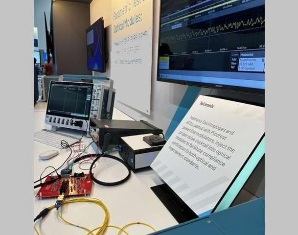
The P2124A supports the QSFP-DD/QSFP-DD800/QSFP112 Hardware Specification 6.3, OSFP Octal Small Form Factor Pluggable Module Rev. 5, and other pluggable transceivers power supply output noise and tolerance testing specifications including AEC cable and optical module sinusoidal power supply noise tolerance. The probe can be used by manufacturers or end-users to verify OEM compliance with the requirements. A remote sense module is provided to support optimum voltage compliance for the DUT.
NOTE: A RAPID CHANGE IN OPERATING CURRENT, SUCH AS A MODE CHANGE CAN RESULT IN A TRANSIENT THAT CAN EXCEED THE LIMITS OF THE TRANSCEIVER. Additionally, usage of a remote sense filter to adjust the power supply voltage level is HIGHLY recommended.
Probe Background
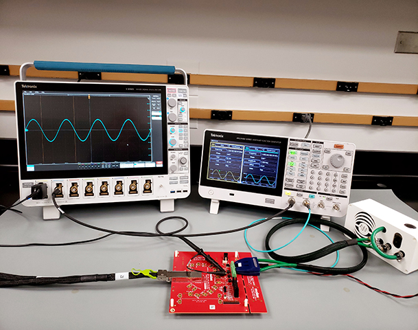
The P2124A High Speed Line Modulator is the first water-cooled probe for electronics testing. Its creation is yet another testament to Plato's axiom that necessity is the mother of invention. Picotest manufactures several Power rail modulators for Power Supply Rejection Ratio (PSRR), Power Supply Modulation Ratio (PSMR) and Power Supply Noise Rejection (PSNR) that are used by engineers to test noise-related performance. These "injectors" allow you to easily impose a modulation signal on a power rail voltage, which is then injected into the device under test (DUT). The input and output noise are then measured and compared to reveal the level of impact and rejection. This enables PSRR, PSMR, and PSNR measurements, which are all measures of how power rail noise appears at the output of voltage regulators, RF amplifiers, and digital channel jitter.
The P2124A release marks a revolutionary change in how test instruments are packaged and implemented. The probe currently addresses high-power, high-injection-level noise immunity testing such as those required for 400G/800G pluggable optical transceivers. Other water-cooled GaN probes are planned by Picotest to address additional test needs.
The rapid growth of the Internet of Things (IoT) and the explosion of cloud computing and 5G, have forced a raising demand on data centers and cloud service providers to increase both network capacity and new solutions to achieve increased data volume required for faster processing, more bandwidth, and increased density without sacrificing reliability. New, higher speed devices, such as optical transceivers, which support these higher data rates, require testing to much higher bandwidths than previously available. This is especially true in the case of testing the signal and power integrity of giga-bit communication interfaces.
Enter the QSFP-DD/QSFP-DD800/QSFP112 Hardware Specification; the test specification for QSFP Double Density 8x and 4x pluggable transceivers. The specification required PSNR testing that was not physically realizable as envisioned. After several discussions with the specification writers, it became evident that a new type of line injector was required. Meeting the interconnection inductance required for the bandwidth limited the interconnect impedance to nanohenries, limiting the interconnect length to fractions of an inch. The interconnecting modulated power cable needed to disappear. The quandary was addressed by Steve Sandler of Picotest, who solved the interconnect issues by downsizing the line injector instrument into a probe form. Many technical challenges, such as the usage of GaN and extraction of the heat from such a small device, had to be solved. This development resulted in the P2124A water-cooled PSNR probe.
Probe Head
Flat connector for solder tabs (wide range)
Other customized heads available
Support for two probe heads
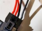
Modulation Electronics Connection: A four (4) wire connection is provided. This includes two wires for power (+/-) for the DUT power and two sense connection back from to the solder tabs on the probe head. The + sense lead is the INSIDE Red lead and the OUTSIDE black lead (thinner gauge wires). It is ok to tie the black ground leads together, but not the red leads as this would cut off the power supply modulation. The probe head connector is a Molex Part Number 1053131104 - Female mating connector. You may connect to this. A mating cable is provided with the Molex Part number connector housing 1053071204. This connector is populated with wired pins (0797582130). Other mating options are possible.
Note: usage of a remote sense filter to provide adjustment the power supply voltage level to account for probe loading is HIGHLY recommended.
Specifications
Typical
Units
Absolute Maximum DC Input Voltage
50 (Probe), 7.5V (Transceiver Application)
V
Peak Current
10
A
Maximum Continuous Current
6
A
Maximum Voltage Drop at 6A
3.5V
V
Output Voltage
Output range is 0V to approximately 3.5V below Vin
V
Modulation Signal Level
0 to approximately the Voltage Drop
V
Modulation Input Impedance
50
Ohms
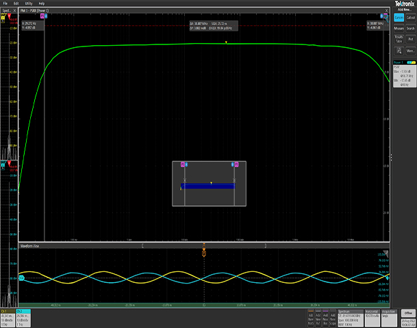
3dB Frequency Response (typical)(0.6ohm resistive load)
30 - 40M
Hz
Modulation Frequency Range
10-250M
Hz
Temperature Range
35
C
Maximum Altitude
6000
Ft
Output Impedance at 6 Amps(typical)
200m
Ohms
Caution: To avoid equipment damage and/or severe injuries death or death do not use this probe close to voltages higher than 50 VAC or 75 VDC.
 `
`
 `
`