Box Contents:
(1) Main Board
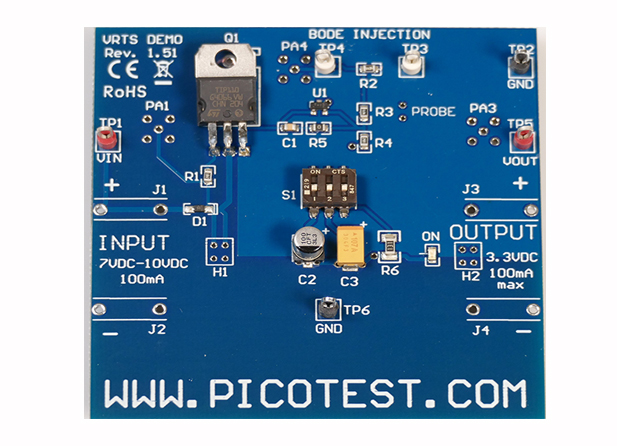
DEMONSTRATION CIRCUIT
The circuit is a discrete BJT voltage regulator with a 7-10V input and a 3.3V output. The BJT is controlled by a TL431 shunt regulator. C1 and R5 provide frequency compensation, R2 is the injection transformer terminating resistor and R3 and R4 are the output voltage sense divider. Two different output capacitors can be selected using S1-1 and S1-2. One capacitor, an aluminum electrolytic capacitor provides excellent phase margin while the other results in approximately 40 degrees phase margin. A blue LED is powered by the output, providing a visual indication of power on and also a load of approximately 20mA. An additional 25mA of load current can be switched on or off using S1-3.
SUPPORTED MEASUREMENTS
| Test | Signal Injectors or Probes Needed |
| PSRR | J2120A or J2111A , J2130A or P2130A , 1-port probe |
| Reverse Transfer | J2111A |
| Bode Plot | J2100A or J2101A |
| Non-invasive Stability | J2102A, J2130A or P2130A, 1-port probe (See Impedance Table 2 below.) |
| Load Step | J2111A, J2130A or P2130A, 1-port probe |
| Noise Density | J2130A or P2130A, 1-port probe |
| Model | Description | Price | |
| VRTS1.5 | VRTS1.5 Voltage Regulator Test Standard V1.5 | $149.00 |
Switches are used to allow various configuration settings for many of the circuits. A summary of the switches is included in Table 2.
Table 2 Switch Functions
POSITION |
ON |
OFF |
||||
| S1 | ||||||
| 1 | C2 - Aluminum capacitor, excellent phase margin – too high for Non-invasive Stability Measurement (‘NISM’) | |||||
| 2 | J2100A or C3 - Tantalum capacitor, poor phase margin – ~40deg can be measured with NISM | |||||
| 3 | J2100Aor130O load resistor for an additional 25mA load | |||||
Copyright © 2023 Picotest. All rights reserved.